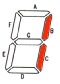
1
CA 0b_1111_1001
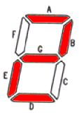
2
CA 0b_1010_0100
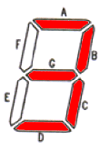
3
CA 0b_1011_0000
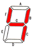
4
CA 0b_1001_1001
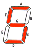
5
CA 0b_1001_0010
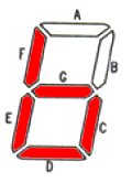
6
CA 0b_1000_0011
 1
CC 0b_0000_0110
CA 0b_1111_1001 |
 2
CC 0b_0101_1011
CA 0b_1010_0100 |
 3
CC 0b_0100_1111
CA 0b_1011_0000 |
 4
CC 0b_0110_0110
CA 0b_1001_1001 |
 5
CC 0b_0110_1101
CA 0b_1001_0010 |
 6
CC 0b_0111_1100
CA 0b_1000_0011 |
First, let me point out that this is handled in the firmware on the PIC.
The displays used in this example are the Common Cathode variety. (That really just means that all the LED segments that make up one digit use the same ground[- or 0v] connection.)Here's an explanation of how this works:
The board has one 7-pin connector for the segments of all the digits. The segment-A wire hooks to the pin for segment-A on all of the digits. This is best wired in a daisy chain fashion. That means you connect the wire for seg-A from the board to the seg-A pin on digit 1, then the seg-A pin on digit 1 is hooked to the seg-A pin on digit 2, etc. We do not use the decimal point.
The segment wire provides the +5v drive for the digit.
Very Important:
There are no current limiting resistors on the board,
so if your digits are designed for less than 5v you should include a resistor on
each segment line to drop the voltage appropriately.
This is done to allow you to choose any size display you want. Be aware that large digit
(generally 2" tall or more, but read the datasheets to be sure)
displays may require more than +5v, and thus also require driver transistors and an
alternate power source. Examples of this will be provided in another document in the near future.
There is also one 6-pin connector that has a wire for each digit. The wire from position 1 of this connector hooks to the common cathode pin(s) of digit 1. The wire from pin 2 hooks to the common cathode pins on digit 2, etc. This is called the digit select pin or digit select strobe.
The digit select pin provides the GND signal for a specific digit. Digit 1 hooks to the common pins on the first digit, digit select 2 hooks to the common pins on digit 2, etc.
To get the number 1 to display on digit 1, the PIC will turn on (to +5v) segments B and C (which make up the digit 1), and then pull low the digit 1 line. That turns on segments B and C for digit 1 only. The rest of the digits are blank at that precise time.
After a few milliseconds the pic will then turn off the segments, and bring the digit select back up to +5v (high) causing all digits to be off. It will then turn on (to +5v) the appropriate segments for digit 2, and pull the digit 2 select pin low (to GND.) That turns on the desired segments on digit 2. This is repeated for each digit in turn. After the last digit, it starts over back at the first digit.
You will notice from this explanation that only one digit is actually on at any given time.
However, because the switching is done hundreds of times a second, it appears that each LED is
showing a different number all at the same time. This technique is called
multiplexing, and is the way most multi-digit displays are implemented.
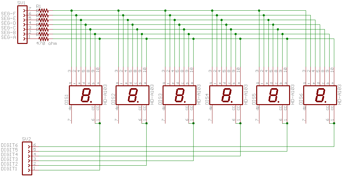
The 470 ohm resistors indicated above are for a typical small digit with a single 2.2VDC LED
per digit segment drawing about 7ma. This size and type can easily be driven
directly from the PIC without requiring any driver transistors.
If you are using other LEDs, the resistor size can be calculated using the tools on
this page.
I will soon be posting an article discussing driving large (over 2 inch high) digits
that are made up internally of many LEDs per segment.
The software in the PIC takes care of the hard work, so it really isn't as complex as it sounds. (At least not unless you are writing the software yourself.)