Whats so cool about that? Well for one thing, this design will be able to support a track of up to 8 lanes with only the extra cost of the additional lane sensors!
Another thing the 16F88 will allow is the (eventual) use of a bootloader, eliminating the need to have a chip programmer, or pins dedicated to ICSP, in order to upgrade the firmware. Instead a bootloader will allow you to download new firmware from the PC using the same RS-232 interface connection already used for sending up scoring info.
Other things in the works are a conversion to the JAL language for the firmware, to make it easer for people to understand and modify if they desire.
I will soon be able to offer preprogrammed chips, and I'm looking into getting PC boards made as well.
In addition, there will be optional features and cost saving options, as well as optional enhancements that can be added if you desire. For example, in every case where there are headers (J1 to J4) you can, to save money, solder wires directly into the circuit. Or for increased flexibility, keep the headers.
| Major Parts: (Prices are from www.glitchbuster.com) | |
| PIC 16F628 | $2.78 |
| 20 MHz Crystal with caps | $0.78 |
| MAX232 | $1.79 |
| 7805 +5v regulator | $0.35 |

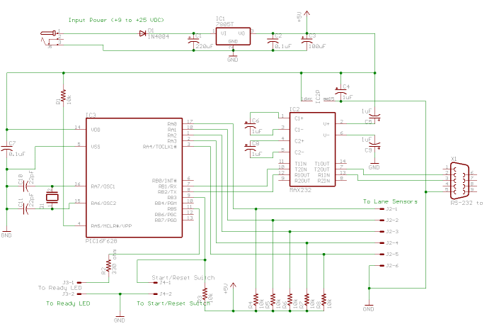
J1 connects to the 9 to 20 volt DC input power source. (Usually a wall-wart.)
J2 connects to the start switch (or optionally a reset button if no start switch is used.)
J3 pins 1-6 are a 6-pin header to which the cable to the sensors is plugged.
J4 connects to the Ready LED.
Also this diagram and board don't show the in-circuit-serial-programming connections.
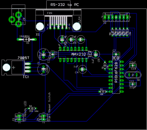
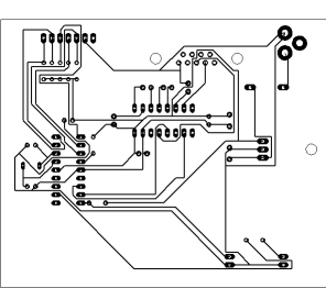
This is a sample board layout:


My Main Pinewood Design Page has some different designs, including a time saving shortcut of spending a little more and using a prebuilt Olimex protoboard.
The PC Software Interface Protocol for communicating with Race Management Software on a PC is documented here.