I've put up this page to share my designs for PICmicro based digital
finish lines for Pinewood Derby tracks.
There are three main variations of the design:
Basic (under $10) unit which only monitors the sensors and interfaces with a
computer for all output and control, and supports up to 5 lanes
Basic unit with blinking LED indicator lights to show finish position
and a reset switch which allows stand-alone operation, in additon to the
computer control.
Advanced unit with 7-Segment LED Display for each lane
Designs 1 can be build using the 18-pin PICmicro 16F628.
Design 2 really needs a 28-pin device, although you could use an 18-pin if you
are willing to give up the ICSP (In Circuit Serial Programming) pins.
Design 3 requires the 40-pin 16F877.
Be sure to check the basic under $10 timer design
page which shows how to build from scratch a basic 5-lane PIC based timer for
under $10!
I've started a Yahoo Group for the discussion of this project.
You can find it here.
Lane Sensors
The Lane sensors used are IR phototransisors (Radio Shack 276-145),
each illuminated from 6-inches away by a 3000MCD Red LED. (Radio Shack 276-307.)
There are two ways to hook them up. You can pull the pin high with a resistor,
and have the phototransistor pull the pin low when illuminated, or you can pull
the pin low with a resistor, and have the phototransistor pull it high when
illuminated. The firmware is configurable to work either way.
On my PC board design I pull the pin high so that I can use a single 8-in-one
resistor network chip for both the sensors and switches, rather than a bunch of
individual resistors,
Here are sample diagrams:
PIC pin pulled high
For this version the output is pulled low by the phototransistor when the sensors
are illuminated. When a car crosses the finish line, the phototransistor turns
off, and the resistor pulls the line high. This is the version used on my PC boards.
Note that the resistors for the sensors are on the board.
They are a part of RN2 (which is 8-resistors in one part) shown in the diagram. You do not need
additional resistors on the track, only the phototransistor.
RN2 isn't on the P40b as I used individual resistors on the prototype.
PIC pin pulled low
For this version the output is pulled high by the phototransistor when the sensors
are illuminated. When a car crosses the finish line, the phototransistor turns
off, and the resistor pulls the line low.
I've found that ultra bright red LEDs work much better than the IR LEDs.
The red LEDs are very close to the IR spectrum, and are much brighter, and being visible, easy to
align and to verify the alignment before each race.
These same phototransistors are available from
glitchbuster.com
for around 50-cents each, with only $1.85 shipping. They have almost all the parts you will need,
and at the best price I've seen anywhere -- a considerable savings over Radio Shack.
You can get 7000 MCD red LEDs from LSdiodes.com
for only $0.60 cents each and $2 shipping. These should work even better, and cost less!
The phototransistor should be mounted in a narrow tube that is one to two inches long
and has been painted flat black on the inside. This reduces
the effect of ambient light on the sensors.
The total distance from the LED to the sensor shouldn't be greater than 6 inches
with the standard IR or 3000 MCD red LED.
A brighter LED may give you more distance.
Alignment of the LED with the phototransistor and tube are important,
since you want maximum signal when the LED is on and unblocked.
Computer Interface
Communication with the computer is done via the serial port. The PICmicros
I used both have built in USARTs. Conversion to RS-232 levels is done using a Maxim MAX232 chip
and four 1uF capacitors. The PC Software Interface Protocol
for communicating with Race Management Software on a PC is documented here.
If you have a newer laptop or computer without a serial port, a USB to serial adapter can be
purchased relatively inexpensively and works fine.
I got mine at the local Best Buy or CompUSA in the PDA section for around $20.
Note, however, that while this will work fine for running a race and talking to
the race timer, it cannot be used with a serial pic programmer for programming
the chip, because it has insufficient voltage for programming.
Power
Power is provided from a wall-wart type 12v
transformer and regulated to 5v with a 7805 and decoupled with several
capacitors, as shown in the design below. Reverse voltage protection is
provided by the 1N4004 diode.
Shortcut
There is a new, even better shortcut option available now.
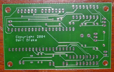
I've had custom PC boards made for the timer.
These are high quality, solder mask coated, double sided boards,
silkscreened with the white component mask showing where everything goes.
These were made by Olimex, the same people that make the P40B board
you can see below. Cost of these boards will be $20 each for
a bare board, or $35 with a preprogrammed 16F877A.
That price includes free shipping within the continental US.
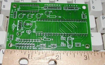
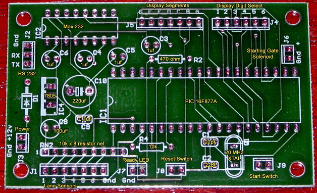
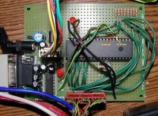
PCB Parts layout - click to supersize. (Board darkened to make labels easier to read.)
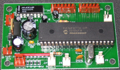
Assembled Board (for 3 lane track) - click to supersize.
The various sized Molex KK connectors around the edges of the board are optional.
To cut costs a little, you can just solder the wires directly into the board.
You will notice that the power jack and RS-232 connector are not mounted on the board.
This is so that you have flexibility in choosing the mounting location for those
connectors for your installation. (This way, the board doesn't have to be mounted
at one side of your enclosure for the power jack and port to stick out, which
was always a problem with the P40B.)
Other than using the custom timer board, if you want to save a few steps, you can buy an Olimex
PIC-P40B proto board
from SparkFun Electronics
for a around $22, which already has most of the parts
in place. It has a DB9 connector hooked to a MAX232 with all the necessary
capacitors, all the power related components, and a PIC16F877A already
mounted and ready to go.
It even has a jack for a wall-wart power supply. (Which you can also get from them for $3 to $6, if you don't want to dig through your junk box for one.)
It also has an ICSP (in-circuit serial programming) connector, which with their
PIC-PG1
for about $8 and the free ICPROG software from Bonny Gijzen
gives you the ability to download the programming to the chip yourself.
All you'd have left to do is solder in the resistors and the lines to the
sensors, and a couple of lines from the MAX232 to the PIC RX and TX pins, and
you'd be ready to go. It doesn't get much easier than that. You could use the PIC-P18B or PIC-P28B, but they
aren't much cheaper, and the 40-pin 16F877A gives you enough spare I/O pins to later add a
7-segment LED Display if you want, for stand-alone operation without a PC.
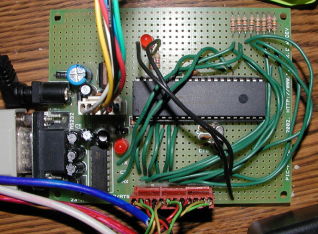
Olimex PIC-P40B Proto Board: (Shown without the PIC 16F877A chip.)
The Design
The lane sensor lines hook to pins 2, 3, 4, 5, 6, and 7 for lanes 1 to 6 of a 6 lane track.
For fewer lanes, use fewer pins. (2-4 for a 3 lane track.)
Run a 10k resistor from each of those six pins to +5v, including pins for any any unused lanes.
For each lane in use run a line from the pin to the emitter of the phototransistor.
Connect the collector of each phototransistor to the +5v. Be sure to remove the jumper
next to the LED on the protoboard, or the LED may affect the Lane 1 (RA0) pin.
On the PIC-P40B, to connect the MAX232 to the PIC, connect PIC pin 25
(RC6/TX) to pin 10 of the MAX232 (the RX hole on the protoboard),
and pin 26 (RC7/RX) of the PIC to pin 12 of the MAX 232(the TX hole), as shown below.
The pins by the Max232 on the P40B are labeled for the computer's RS-232 pins they correspond to,
so the Max232 RX goes to the PIC TX, and the Max232 TX goes to the PIC RX, as seen below.
Click the images to see the super-big versions.
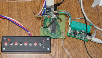
Below is my complete development test environment.
It shows the "track simulator" I put together for testing and debugging
the firmware without needing a real track at my desk.
The programmer in the picture is a
kitsrus.com kit 150 USB programmer,
but I also use the Olimex PIC-PG1 serial programmer. With the USB programmer, I can leave it
hooked to the ICSP connector and keep the P40 RS-232 connector hooked to the com port,
without having to switch the serial cable back and forth and shut down hyperterminal every
time I want to load a new compile of the firmware. Plus the USB programmer is much faster,
programming and verifying the whole chip in about 5 seconds.
(Click image to supersize)
Unless you are using the P40B, you'll also need a regulated +5v power source,
like the one at the lower left of my schematic.
Plans for another good one can be found
here.
The advanced version looks like this:
Click on the reduced schematic to see the full sized version. It is large, so
your web browers may reduce the image. If you are viewing it full size, it should appear clear and crisp not fuzzy or distorted.
Note that the starting gate pin should not be hooked directly to a relay or solenoid, but to a driver transistor.
Here is an example using a MOSFET driver transistor. (The IFL540N is around $1 from glitchbuster.com)
The diode in parallel with the solenoid is also important, as it prevents the reverse current spikes
that would otherwise occur when the solenoid switches off.
To see how the 7-segment display hookup works, see How does it drive six 7-segment displays using only 13 pins
for an explanation of digital display multiplexing. Note also that there are no current limiting resistors
on the board. This was done to allow maximum flexibility in your choice of display hardware, however
you must be sure you provide an appropriate voltage level for the 7-segment displays you are using. For small digits
that just means appropriately sized current limiting resistors. For large size digits that means
driver transistors and a higher voltage source. My next few goals for this project are to construct
a sample kind of "reference standard" small digit display, as well as a design for a large digit display made up of of discrete LEDs, and one using
3" 7-segment LED's modules.
(Probably these from jameco,
as they seem to be the biggest bang for the buck in the large LED Digit Display category. Also they are about half the price of the equivalent from DigiKey.)
If you decide not to go the SparkFun/Olimex PIC-P40B route, the best place for the
individual components is
glitchbuster.com.
The owner, Randy Jones, offers the best pricing I've ever seen, prompt service,
and really cheap shipping too! ($1.85 shipping to anywhere in the US!)
The Firmware
You can download the hex firmware image here, or the
full JAL source code here.
The firmware is "soft configurable" for several hardware options. I've written a MS Windows program
to set up and configure the firmware. You can download the excutable here
or a zip file containing it here. The settings
are stored in the eeprom on the timer, so you should only have to perform the setup once.